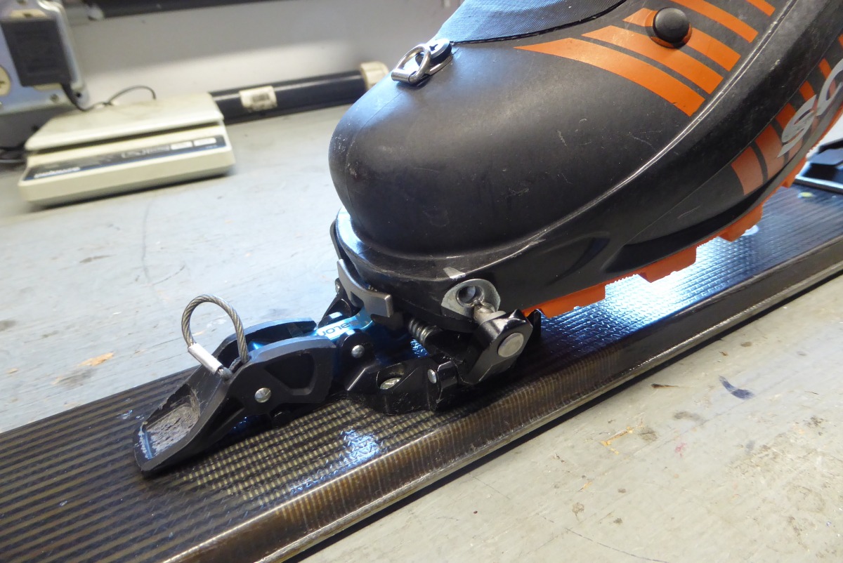
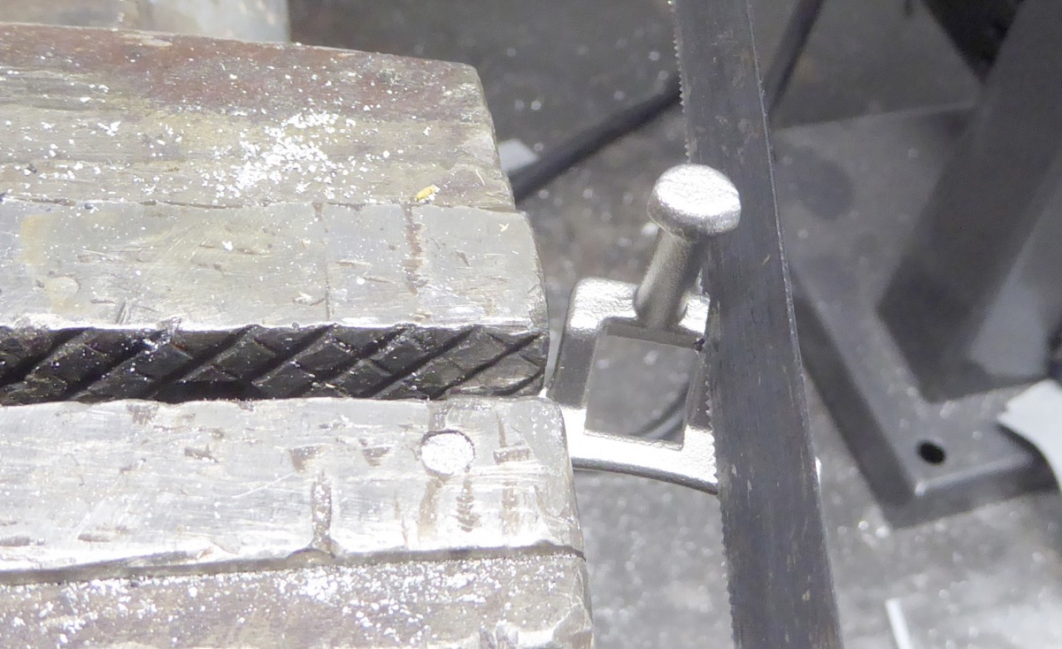
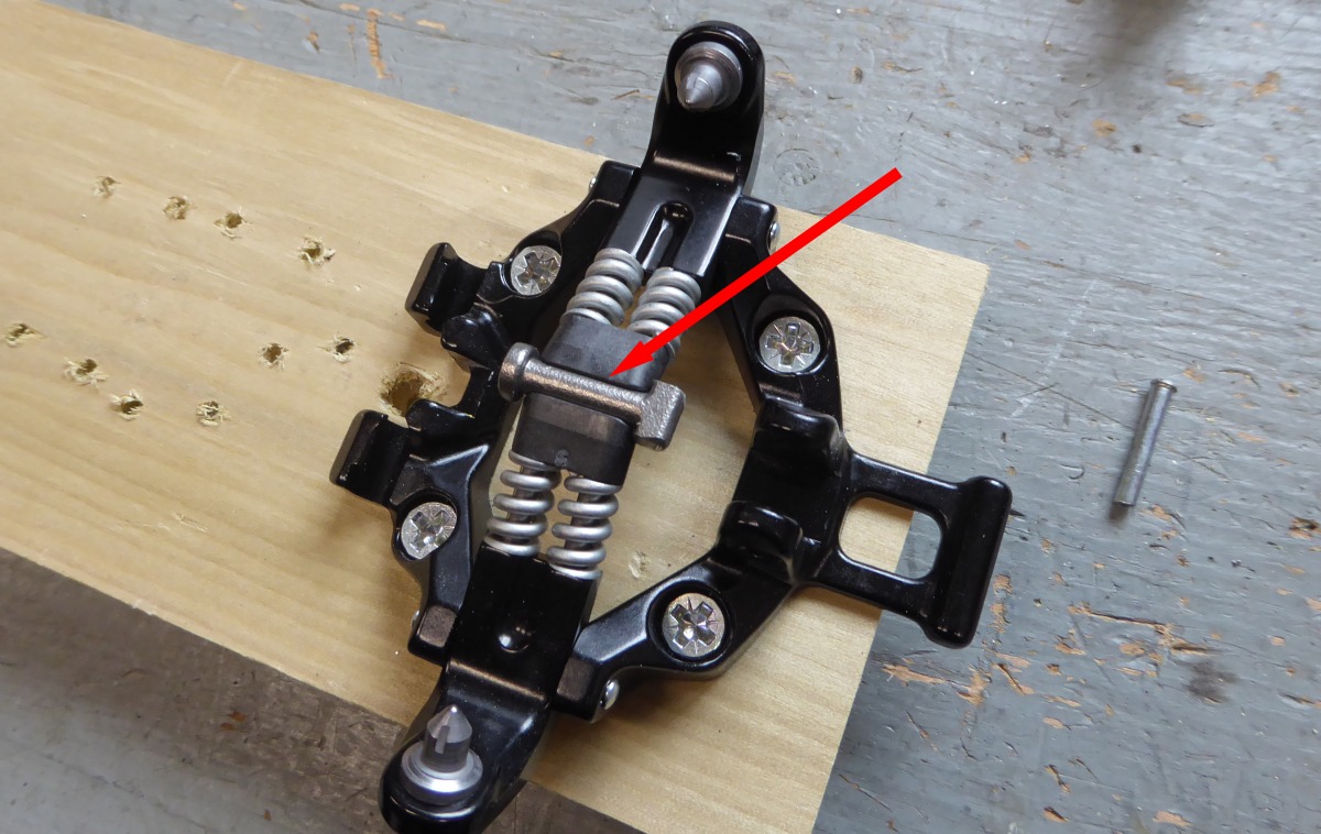
Scarpa F1 with Atomic Salomon touring binding. The boot toe locator stop, as pictured, just doesn’t work for me. Ectomy time in the Rockies.
It’s no secret that the Atomic/Salomon Backland/MTN (Atomisal) is one of my favorite ski touring bindings. I’ve experienced near flawless performance going on years now, with one concern. Maybe it’s my personal style, or physical limitations, but the boot toe locator doohickey always seems to get in my way more than it helps me — specifically with my Scarpa F1’s. While I suspect many of you don’t have this problem, for the record and in the storied tradition of WildSnow, here is how I remove the boot locator. In detail. Jokes about extreme gear mods accepted, but please be kind.

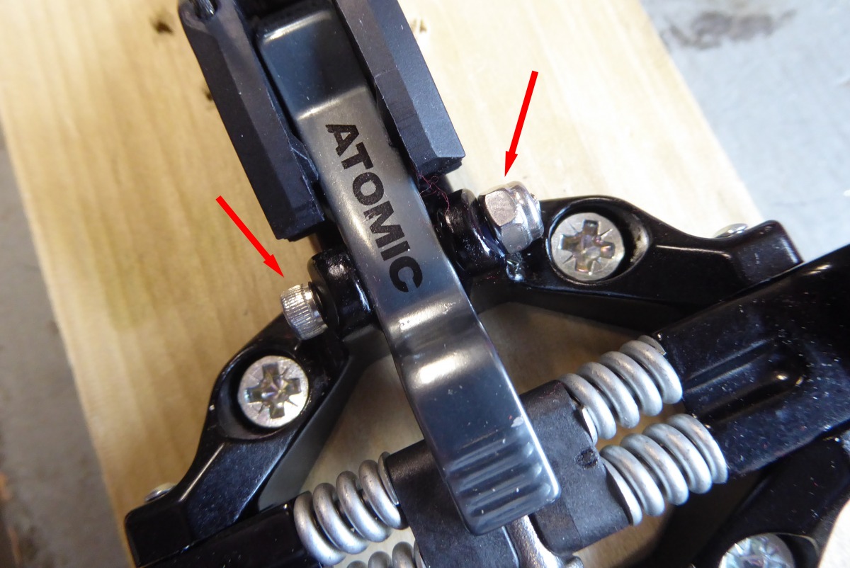
Step 1: mount Atomisal binding toe on a board and fixate the work.
Note: If you have or construct a binding spacer like the one I picture below in step 13, that holds the binding toe in the on-boot position, you can install the spacer from the start and eliminate some of the opening-closing steps below. I thought it more instructive to present most of this how-to without the spacer. If you care to make a spacer, experiment and you’ll easily see how it helps. To be clear, the spacer imitates having a boot clicked into the binding.
Step 2: grind the head of the lock lever pivot pin so it’s flat, and just thick enough to avoid accidentally grinding the aluminum lock lever body. Instinct told me to do this on the non-peened side, assuming it would be less work-hardened. Probably doesn’t matter. Important: Do this step with the binding in the closed (as if on boot) position. Otherwise you risk the binding springing apart and shooting parts across the room. Having taken tech bindings apart before, I should have remembered this step, but I took one for the team and almost lost one of the small black-plastic parts.

Step 3 & 4: center punch, then drill the head off the pivot pin. I stepped up from a 1/16″ bit to something just about as large as the pin head.
Step 5: drive the rivet out, use a wrench socket (not pictured) as support to receive the driven pin, to avoid damaging the binding.
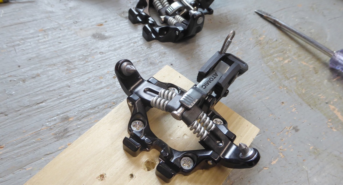
Step 6: Cover the binding with a heavy towel or plenty of shop rags — as padding and parts retention. Be sure the edges of the cloth are down on your workbench, then use a flathead screwdriver to pop it up into the open position while gently pressing down with your padded hand to attenuate the explosion. As you do this, the left and right parts of the mechanism will come apart somewhat violently. Watch your hands, and don’t do this in a place where you could lose small parts.
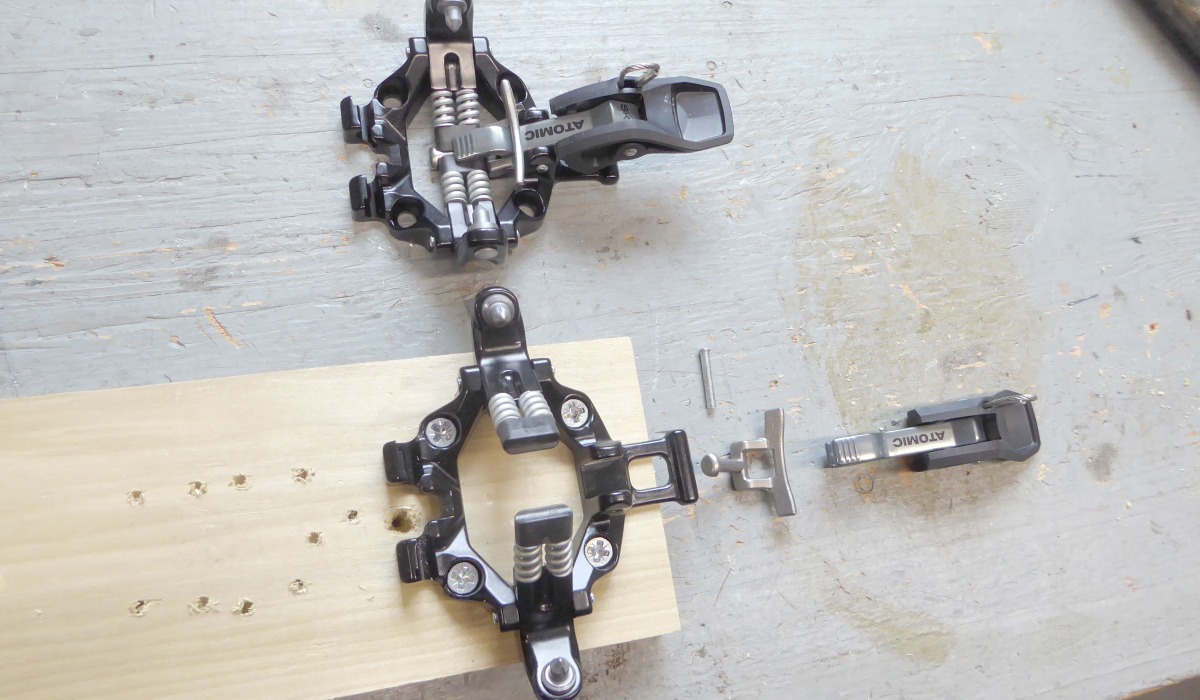
Step 7: remove the lock lever and boot toe locator stop. If the springs and small black plastic bits have come off, reassemble so the binding appears as pictured.
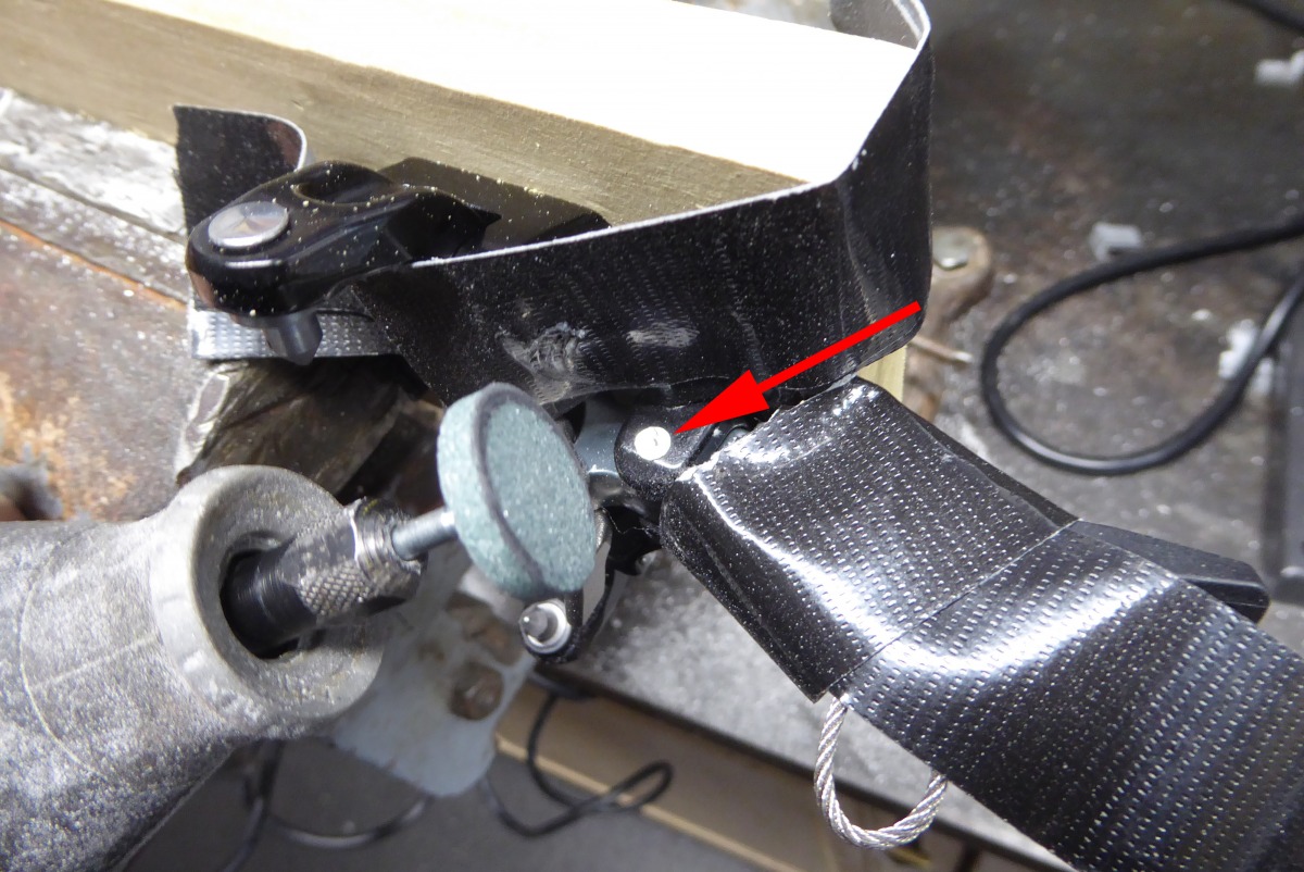
Step 8: Cut the boot toe stop off the mushroom shaped stud. IMPORTANT: While cutting, do so in such a way as to leave a long metal nib perpendicular to the stud shaft. After cutting, smooth the edges with an appropriate tool See next two photos regarding cut length.
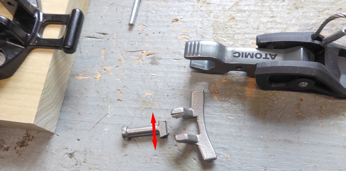
Arrow shows where you need to maintain length of metal nib perpendicular to the stud shaft. The nib prevents rotation of the stud after it’s installed in the binding. Take your time with this, a few millimetres longer than what’s shown here would be ideal.
Another view. Again, I cut it a little short.
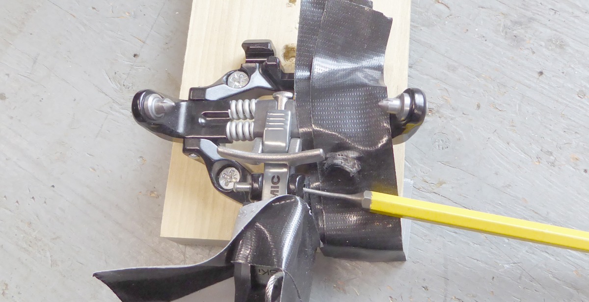
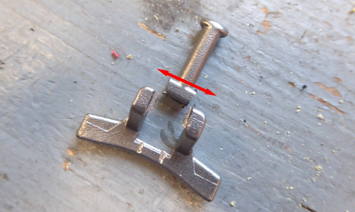
Step 9: Drill out lever and chassis pivot pin holes to 3.5 millimeter, this is slightly over-sized from stock, to fit a 6-32 x 1″ socket-head stainless steel bolt.
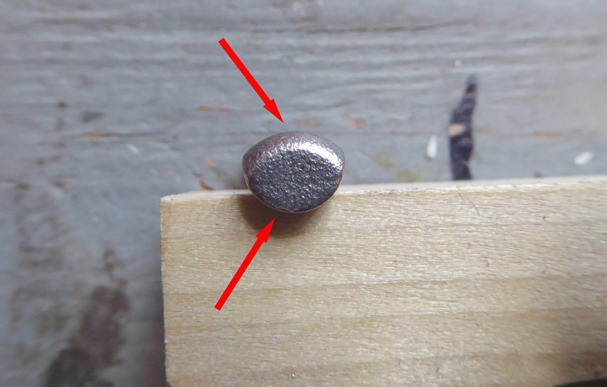
Step 10: Examine the center stud head. When you reassemble, the reduced height side needs to face up, compare to non-modded binding.
Step 11: carefully position the center stud between the plastic bits. Again, compare to non-modded binding.
Continuing step 11, binding assembled, line everything up as close as you can to factory positions, as your next step is to snap the binding closed, which will bring the lock lever close to proper position.
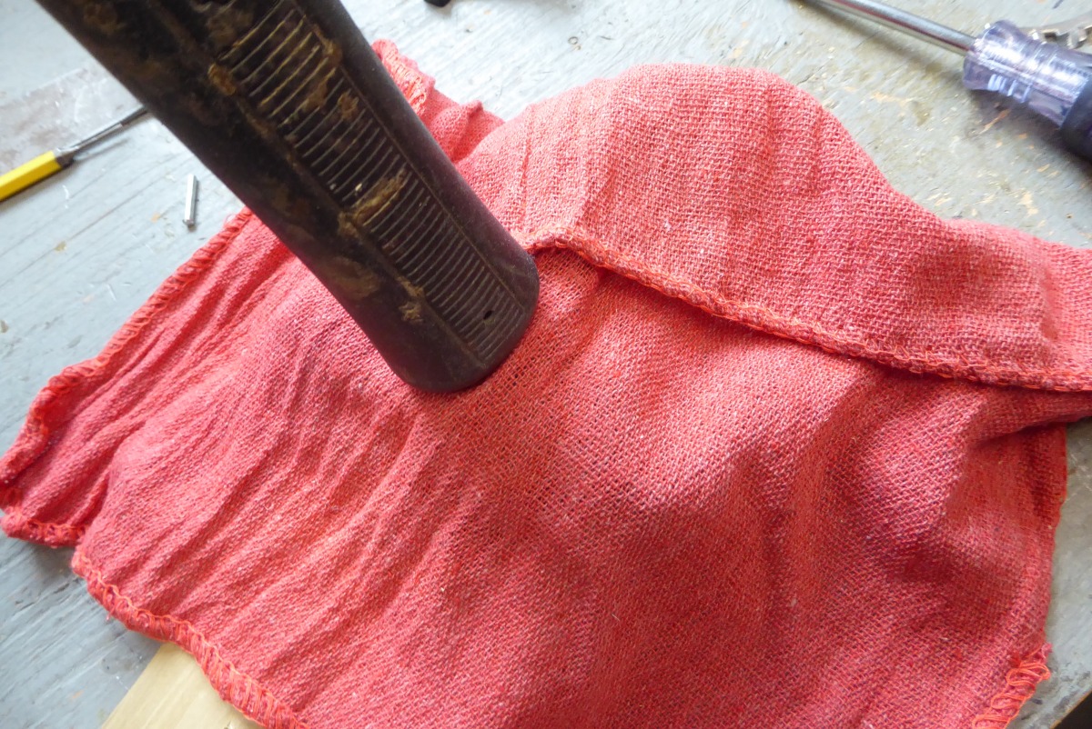
Step 12: With the binding assembled, and in the open mode, cover again and press down the center until it pops into the closed (on boot) position. The cover is insurance, in case you mess up, the binding pops open, and parts take flight.
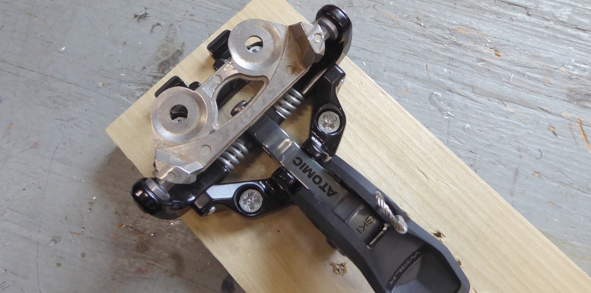
Step 13: Okay, it’s getting tricky now. On first glance, you’d think you could just insert the new pivot bolt and be done with it. Not so fast. The pivot hole in the lock lever won’t quite line up with the holes on the chassis. To remedy, you need to hold the binding in the on-boot position. I use a sample boot fitting for this, but an actual boot will work. CAUTION: While inserting the spacer or boot, don’t attempt to completely open the binding over-center. If you do so, it’ll explode. Instead, gently insert the spacer or boot while opening the binding as little as possible.
Ah, finally. While manipulating the lock lever a bit for final alignment, insert the stainless steel socket-head 6-32 x 1″ bolt, dab the threads with thread locker, and finish with a stainless locking nut.
WildSnow Wrench Rating: 9/10.
Weight reduction per binding (since someone will ask): 8 grams.
WildSnow.com publisher emeritus and founder Lou (Louis Dawson) has a 50+ years career in climbing, backcountry skiing and ski mountaineering. He was the first person in history to ski down all 54 Colorado 14,000-foot peaks, has authored numerous books about about backcountry skiing, and has skied from the summit of Denali in Alaska, North America’s highest mountain.